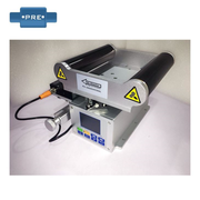


Electronics Line Guiding System
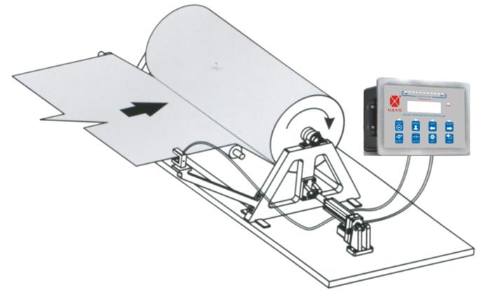
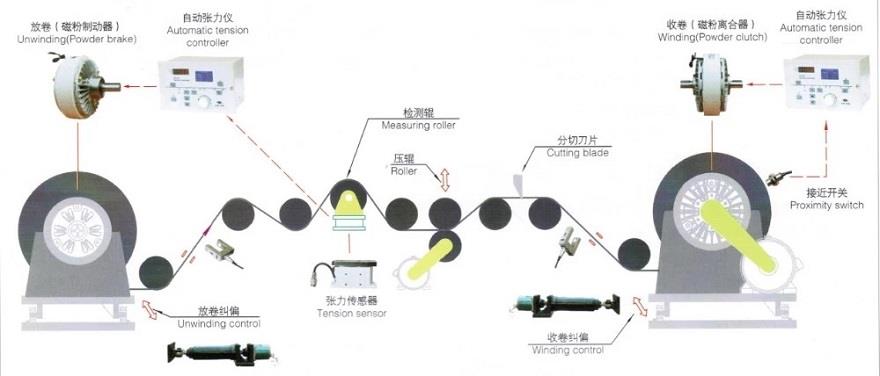
Winding guide application diagram The picture on the left is to align the edges of the web and roll it up. The edge sensor is attached to the take-up reel and a fixed reel is mounted between the sensor and the take-up reel. You don't have to worry about the offset of the web, because the...
Winding guide application diagram
The picture on the left is to align the edges of the web and roll it up. The edge sensor is attached to the take-up reel and a fixed reel is mounted between the sensor and the take-up reel. You don't have to worry about the offset of the web, because the sensor that is attached to the reel always tracks its edges so that it can align the edges of the web and roll up.
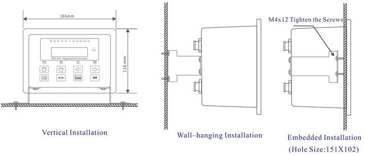
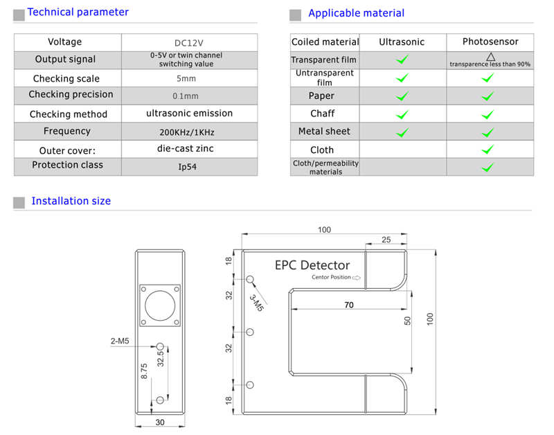
Installation :
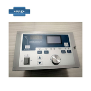
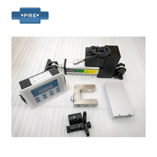
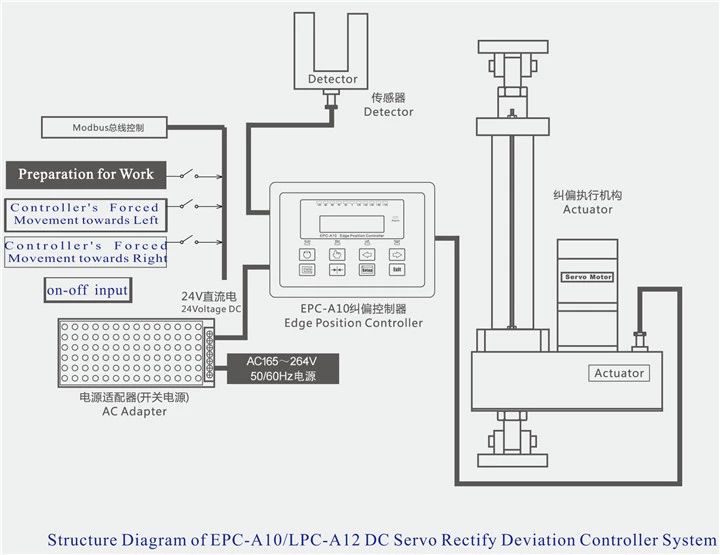
Overview of the working principle of intelligent guide system (guide control device)
Intelligent guide system (guide control device) can track lines, center lines and edges, with good functionality and adaptability; there is no requirement for the density of the coil, and it can be used in coils of different colors. However, it also has a good rectification function in the transparent coil. The correcting system is used in the process of correcting the deviation but the light is used for measurement. This method is very accurate and can be electrically measured with double light. If it is in a bilateral working state, even if there is a phenomenon of material breakage, it will have no effect. Its operation mode is more flexible, you can choose three modes: manual, automatic and reset. And he used a limit device, which has a good protection.
The front and rear sections of the transceiver are not smooth, resulting in the loss of many materials and subsequent processing difficulties. The speed of the corrector can be adjusted to low speed correction. When the material winding speed is relatively high, then the speed of the correcting motor can also be adjusted to high speed correction. Adjusting the frequency can adjust the speed of the correction and correction system. The photoelectric-to-edge line-to-line device can solve this problem.
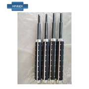
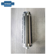
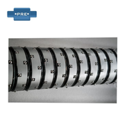
Guide sensor
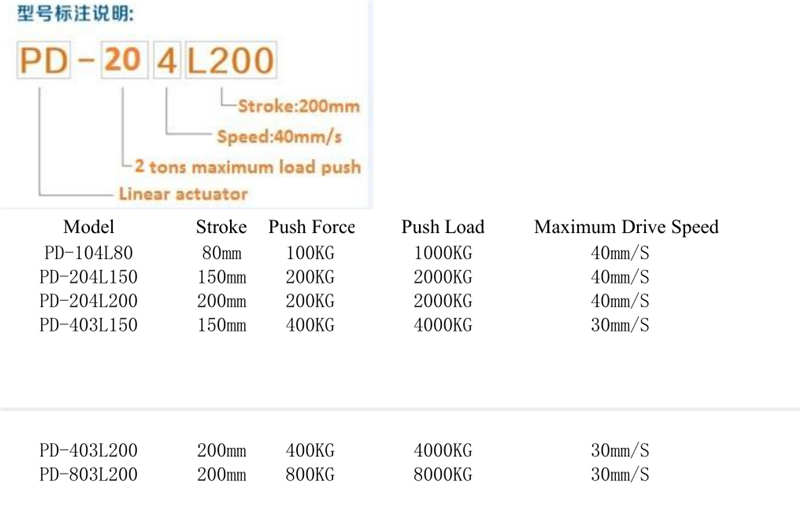
The guide is used for: coating machine, self-adhesive machine, laminating machine, slitting machine, rewinding machine, packaging and printing machinery, etc. The driver of the corrector has a drive limit. For all the correctors, the positional offset within a certain range can be corrected, and this range must be smaller than the drive limit of the drive. The limits of the drive can be adjusted according to the needs of the user. Most drives have positive and negative drive limits of how many millimeters.
The intelligent rectification system (guide control device) takes signals from sensors placed in appropriate positions on the coil line, processes and amplifies the signals, and then supplies them to the actuator; the appropriate output operates the electric actuator. The drive thereby positions the corrective correction system components to maintain the desired state of the web. The correcting controller compares the signal with the set signal, and according to the amount of deviation, the controller outputs a proportional proportional signal to the electric drive for immediate correction. The correction system provides several different detection methods: edge detection, follow-up or alignment. The drive system uses low-speed synchronization, variable frequency speed regulation, stepping and servo motor drive, and the drive stroke and the coil offset are strictly proportional.
Application
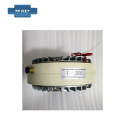
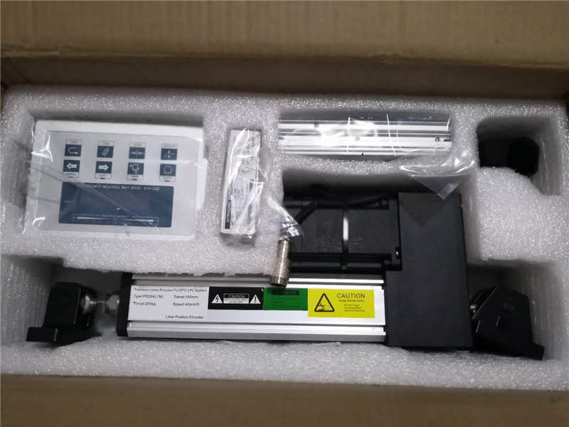
Packing
Order Details
Item Name |
Pivot Web Guide Systems for unwind and rewind |
|
MOQ(Minimum Order Quantity) |
1Pc |
|
Lead time |
3-5 days after receiving the deposit |
|
Calculated Weight |
Depend on model set |
|
Package |
Carton/Wooden Box |
|
Price Term |
EXW,FOB, CIF, etc |
|
Payment term |
TT,L/C,Western Union |
|
Country of Origin |
China |
Hot Tags: electronics line guiding system, China, manufacturers, suppliers, factory, quotation, pricelist, buy