Tel: +86-134-31394972
E-mail: sales@pre-webguidesystem.com
Tel: +86-134-31394972
E-mail: sales@pre-webguidesystem.com

Web guide system controllers in industrial inspection and automatic control systems The application of guide system controllers plays an extremely important role in industrial automation production. In the processing industries of petroleum, chemical, electric power, steel, machinery, etc., they are responsible for the equivalent of people's sensory organs in their respective jobs. They complete the detection of various information as needed every moment, and then put a lot of The measured information is fed back through automatic control, computer processing, etc., for control of production process, quality, process management and safety. In an automatic control system, the combination of an electronic computer and a sensor plays a key role in achieving a high degree of automation of control.
")
The operation of the strip edge control can be either automatic or manual, and its control electronics amplifier circuit is shown in Figure 5.1. In the figure, φ is a photodiode, Rt is a temperature-compensated thermistor (in the photoelectric measuring head). The maximum input value of the voltage amplifier V1 is ±10 volts, and the output is also ±10 volts. The ratio of the control system is adjusted by the potentiometer W1. Range, use potentiometer W2 to adjust the sensitivity of the control system (ie, the magnification of V1). The switches K1 and K3 are in the automatic operation state when they are on, and the manual operation state when they are below. For manual operation, place the transfer switch in the manual position (K1 is below) and press K4 or K5 to move the uncoiler (or coiler) to the drive side or the operating side. When the button K2 is pressed to the automatic centering state, the uncoiler (or coiler) can be mechanically centered (in the automatic state). At the output end of the final stage power amplifier V2, it is directly connected to the electro-hydraulic servo valve coil L, and V2 outputs 0~300 mA. In order to improve the sensitivity of the servo valve and reduce the inertia, the AC voltage of 50 Hz is connected to the terminal F, so that the electro-hydraulic servo valve is always in the vibration state. Once there is a control signal, the piston can quickly reach the control position. The amplitude of the piston can be adjusted by potentiometer W4. When the strip on the uncoiler (or coiler) is in the normal position (ie, the centering position), the optical signal irradiated on the phototube φ is converted into a voltage signal Ur1 and the electron amplifier is added to a reverse voltage Ur2. They cancel each other out so that the signal applied to the V1 input is zero.
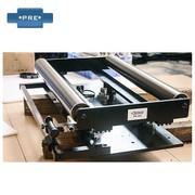
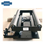
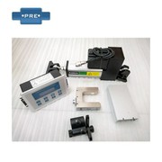
Web guide system principle: The infrared light/ultrasound/laser/visible light is monitored by the guiding sensor B, and the signal is sent to the controller A. After the controller finds that the coil has a positional drift, the controller D controls the swing of the web guiding frame C to correct the position of the coil according to a command preset by the controller. The automatic material rectification system uses a photoelectric sensor to detect the edge position of the coil, and sends the measured position error signal to the controller. After the control unit judges the process, the drive motor is controlled to correct the coil at the deviation position to the correct position. . The FIFE guide System offers several different detection methods: edge detection, follow-up or alignment. The drive system uses low-speed synchronization, variable frequency speed regulation, stepping and servo motor drive, and the drive stroke and the coil offset are strictly proportional. The system can also be used with different probes to suit the needs of different coils, such as: infrared photoelectric, analog infrared photoelectric. The microcomputer digital controller provides precise control of the system's functions.
Previous: What To Pay Attention To When Using The Web Guide System
Next: The Accuracy Of The Photoelectric Corrector Is Determined By Three Factors