Tel: +86-134-31394972
E-mail: sales@pre-webguidesystem.com
Tel: +86-134-31394972
E-mail: sales@pre-webguidesystem.com
After the photoelectric detection head, motor, limit switch and power supply connection of the photoelectric correction sensor correction system are accurate, the operation can be carried out as follows:
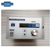
1. Turn on the power switch, and the bias indicator will start flashing for three seconds in a disciplined manner, and the buzzer will sound three times; then the state of the controller before the previous shutdown.
2. If the tape is first adjusted, switch to manual mode. Press the “→←” button to make the motor move, aim the light point of the photoelectric head to the edge of the tracked edge or line; and adjust the acuity of the photoelectric head so that the indicator light has obvious bright and dark changes in the color code.
3. Then you can run under the “automatic” method, at which point the movement of the material is too fine. If it is only moving towards one direction (the normal environment should be alternately moving in the horizontal direction), you need to press the polarity button to change in time.
4. Others can decide the operation of the key when the automatic method is made, so that the motor and the thing are at the matching frequency. For example, in a single photoelectric method, the speed should be increased when the speed is fast.
5. If a very-limit action is generated, the buzzer will alarm and the motor will stop running immediately. Through the introduction of the above matters concerning the operation of the photoelectric sensor guide system, I believe that you have a deeper understanding of the photoelectric guide sensor!
A common automatic photoelectric corrector control system can be implemented. However, if the material roll speed needs to be changed, and the ordinary corrector can not change the rectification speed, it will lead to the phenomenon that the curling cannot be corrected, the unevenness of the material thickness and various mechanical damages, resulting in the material on the production line. Movement and one-way deviation.
As a result, the processing action in the middle section is not easy to match, or the transmission and reception of the front and rear sections are not smooth, resulting in loss of many materials and difficulty in subsequent processing. The photoelectric-to-edge line-to-line device can solve this problem.
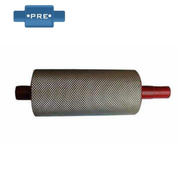
The corrector is used for: coating machine, self-adhesive machine, laminating machine, slitting machine, rewinding machine, packaging and printing machinery, etc.
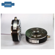
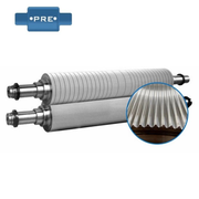
Principle of automatic photoelectric corrector: The infrared light/ultrasound/laser/visible light is monitored by the corrector B, and the signal is sent to the controller A. After the controller finds that the coil has a positional drift, the controller D controls the swing of the correction frame C to correct the position of the coil according to a command preset by the controller.
The automatic material rectification system uses a photoelectric sensor to detect the edge position of the coil, and sends the measured position error signal to the controller. After the control unit judges the process, the drive motor is controlled to correct the coil at the deviation position to the correct position. . The automatic photoelectric corrector is a closed loop controller, controller, sensor, linear guiding mechanism to form a basic part of closed-loop control.