Tel: +86-134-31394972
E-mail: sales@pre-webguidesystem.com
Tel: +86-134-31394972
E-mail: sales@pre-webguidesystem.com

(1) The direction of the controller opening towards the worktable;
(2) The receiving pole is facing upwards, and the emitter is down; (from the dialog box, the receiving pole is very gray and black, and the emitter is milky white)
(3) When the required coil diameter is at least to larger, the left and right movement trajectory of the amorphous strip must be between the emitter and the receiver of the photoelectric switch;
(4) The front, rear, left, and right installation positions of the controller are between the winding head and the channel guide roller. It must not be affected by the guide plate;
(5) The upper and lower parts of the controller must ensure that the total width of the specification and model of the amorphous strip is within the range of the inspection line.
Install the sound card rack centering phase sensor: First, the hydraulic cylinder is first to promote the coiler to be in place, then the fixed phase sensor is fixed at a certain position of the coiler base, and then the magnetic induction copper sheet of the controller is welded on the coiler. Turning to the headlight between the two, one edge of the wide square side of the copper sheet points to the middle of the controller, and the long side should cover the controller to ensure that when the hydraulic cylinder moves up and down, the magnetic induction surface of the copper sheet can change positive and negative. The controller gap is 4~6mm.
1. System adjustment.
1. After checking that the system wiring is correct and correct, first cover and operate the switch power isolation switch, and dial the phone on the workbench to indicate the termination of the gasoline pump, the termination of the refrigeration and the termination of the correction device. The power amplifier is connected to the servo motor proportional valve: valve position feedback controller data The signal is as follows:
231: +15V switching power supply in operation
232: 0V switching power supply ground
233: -15V working switching power supply
234: Opinion feedback output
The opinion feedback output matches the working voltage data signal in different installation states as follows:
Correction device termination: -8.5V
Press to terminate: 0V
Manual shift left: -4V
Manual right scale: +4V
Sound card rack centering/automatic correction device: 0V up and down
If the photoelectric correction controller appears to be stable in one azimuth and the other azimuth hydraulic cylinder vibrates throughout the operation, adjust the W4 in the power amplifier for a few clockwise rotations.
2. Adjust the position of the motor and then cover the driving force switch power isolation switch, press the gasoline pump start button, and observe whether the motor turns clockwise, or adjust the position.
3. Adjust the working pressure of the system to adjust the speed control valve, the working pressure of the system is 7Mpa up and down, and then lock the rocker screw cap.
4. Adjust the centering button of the sound card rack to the center of the circle, the coiler should return to the negative correlation termination, if the sound card rack is biased to one end, adjust the zero resistor W6 in the PID control board, and use the digital multimeter to monitor the DC working voltage file. Servo controller output terminals 10 and 11 until the working voltage value is zero. If the coiler cannot be stabilized at first, it indicates that the system position is reversed, and then replace the centering data signal input terminal integral circuit or inverting terminal. Adjust W6 to make the coiler to be negatively correlated. Adjust the gain value resistor W5 (adjust clockwise to increase the gain value) to make the system operating speed suitable. If the gain value is too low, the coiler moves slowly; the gain value is too high If it is high, the system will cause a resonant circuit and the sound card rack will vibrate when it is centered.
5. To adjust the manual mode, press the manual mode to move left and manual mode to move to the right, and observe whether the hydraulic cylinder is in a posture and moving stably. If crawling occurs, it will be the main cylinder gas function, then put the servo motor proportional valve on The air nut is loosened, and then the hydraulic cylinder continues to exercise several times to let the air outlet discharge some oil. After squeezing the air, the nut is locked.
6. Adjust the automatic correction device
To adjust the zero position of the control panel, first block the light curtain sensor in half, and the photoelectric data signal output is zero, then loosen the lock of the control panel zero resistor knob in the opposite direction, and then adjust the joystick to the middle scale 5, the resistor output Zero (video signal ±12VDC).
The dimming curtain sensor opens the display cover of the modem on the side of the EPC controller, and then uses the digital multimeter working voltage to measure the photoelectric input data signal No. 6 terminal matches No. 10 (data signal ground), safety light curtain When it is not blocked, the data signal is up to 1.5VDC. When all the light sources are blocked, the data signal returns to zero. The photoelectric data signal is demodulated, enlarged, and transformed into a data signal of output standard working voltage to the servo controller, and the output point 9 is connected to the data signal ground. For all blocked light sources and all unblocked light sources, the output data signal changes between -10V and 10V. If it is different or the data signal amplitude value is wrong, you can adjust the zero resistor W8 and the gain value resistor W7 to keep the best condition. After adjustment, seal the metal material cover.
Adjust the servo controller
The basic principle of the EPC correction system for adjusting the position of the correction device is that the coiler follows the transformation of the amorphous strip, that is, the moving position of the coiler is consistent with the deviation of the amorphous strip. Otherwise, it can be changed according to the adjustment system position. It is very simple to change The photoelectric data signal 205 of the input point of the servo controller is replaced by the integral circuit terminal and the inverting terminal.
Adjust the precision of the correction device. Adjust the gain value resistor W4 of the correction device (clockwise adjustment, the gain value increases) to improve the precision of the system correction device, the gain value is low, the response is slow, the hydraulic cylinder low-frequency oscillation, the amorphous strip coil Uneven; if the gain value is too high, the system will cause resonant circuit and high-frequency jitter. Generally, the system gain value is higher but it is not necessary to oscillate as the best working part.
Adjust the zero position of the correction device to enter the data signal (terminals 205 to 110) to zero, zero resistor to zero, and the ammeter with deviation mark must be reset to zero, otherwise the zero resistor W3 in the servo motor board can be adjusted to maintain and move up and down For the obstructions on the light curtain sensor, the hands of the watch should shake up and down, and the positive and negative poles should change.
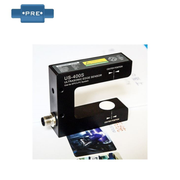
2. Supply PS-500/photoelectric correction controller
PS-500 photoelectric correction controller
PS-500 photoelectric switch is based on the invisible light beam-correcting device controller. It is suitable for the edge-tracking application of waterproof membranes or the line-tracking application of fully transparent materials.
Performance parameters of photoelectric correction controller:
Supply working voltage: DC10-30V output data signal: dual 0-5V, dual NPN power switch data signal
Inspection scope: 5mm Inspection precision: 0.05mm
Inspection method: photoelectric to spotlight source: high-definition blue LED/infrared Irda
Carrier frequency/response frequency: 100KHz/1KHz
Waterproof rating; IP54
Function characteristics:
1. The 100K frequency carrier number will not be harmed by the environment.
2. Inspection scope is 5MM, inspection precision is 0.02mm
3. Appropriate for line tracking applications of not fully transparent and fully transparent plastic film
4. Invisible light beam
5. High reliability and high precision
6. Applicable modulus/power switch output, can be matched with EPC-A10 or EPC-A12 correction device control board
Previous: Interpret The Function And Application Of The Web Guide System
Next: What Is The Operating Process Of The Photoelectric Automatic Correction System