Tel: +86-134-31394972
E-mail: sales@pre-webguidesystem.com
Tel: +86-134-31394972
E-mail: sales@pre-webguidesystem.com
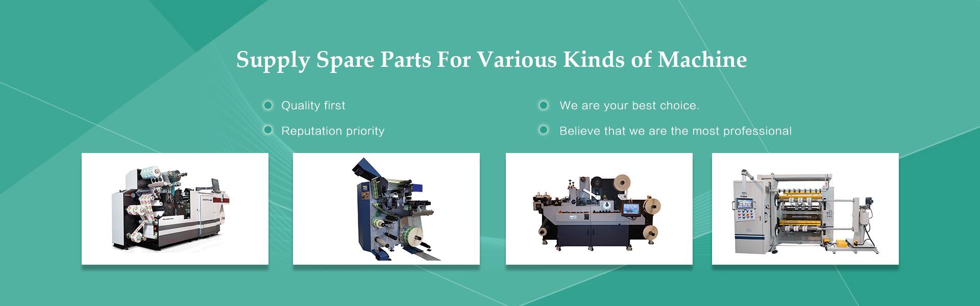
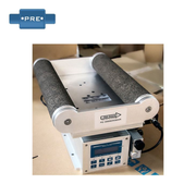
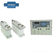
The slitting rewinder includes a frame and a slitting device, a tape feeding device, a tape unwinding mechanism and at least one tape winding mechanism assembled on the frame; the tape winding mechanism includes a bonding device, a tape roll, and a drive tape roll The rotating tape motor, the tape roll is equipped with a core, and the bonding device is used to bond the head end of the material tape in the roll groove of the core; the tape releasing mechanism includes a tape releasing roller, and the tape releasing roller is equipped with The master tape roll; the slitting device is used to split the mother tape output from the master tape roll into at least two sub-belts; the tape feeding device includes a belt feeding roller, a belt feeding motor, and a pressure roller, and the belt feeding motor drives the feeding The belt roller rotates on a fixed axis, and the sub-belt passes between the belt feed roller and the pressure roller. The use of slitting and rewinding machine can effectively reduce the structural requirements of the master tape roll, and the master tape roll can be directly slit and rewinded in a slitting and rewinding process to obtain the product, and the production efficiency can be increased by several times or even dozens Times, it is also conducive to the standardized production of products.
Slitting rewinder rewinding mechanism, the tube core is located between and in contact with the two supporting rollers, the pressure roller presses the tube core, the swing arm cylinder is hinged on the frame; one end of the swing arm is connected to the swing arm The cylinder piston rod is hinged, the other end of the swing arm is connected with the pressure roller of the product, the middle of the swing arm is hinged with a support shaft, the support shaft and the pressure roller are connected by a timing belt; the transmission shaft is connected with the support shaft by a timing belt; The bridge shaft is connected to the drive shaft through a timing belt; the second bridge shaft is located between the first bridge shaft and the two supporting rollers, and the gear on the second bridge shaft is connected to the gear on the first bridge shaft and two The gears on the support roller mesh; the insert plate is located on one side of the pressure roller. The mechanism can realize the synchronous rotation of the pressure roller, the supporting roller, and the paper roll, and can realize the adjustment of the parallelism between the pressure roller and the supporting roller, and can effectively improve the cutting quality of the paper roll.
Previous: Introduction To The Advantages And Structure Classification Of Aluminum Alloy Guide Rollers
Next: Introduce Various Common Guide Rollers And Their Corresponding Performance