Tel: +86-134-31394972
E-mail: sales@pre-webguidesystem.com
Tel: +86-134-31394972
E-mail: sales@pre-webguidesystem.com
1. Display: The photoelectric sensor records the specific wheel position, which is transmitted to the control system via the transmission cable. After the system calculation and detection, the result is sent to the display system, which displays the specific position of the cart and the distance between the legs.
2. Detection of bias: The control system refers to the left and right actions of the cart. When the left row, the two legs are biased. The data transmitted by the faster outrigger is larger. The leg is displayed; when the right row is shifted, the legs are offset, and the data transmitted by the faster leg is smaller, and the system defines the leg as leading and displays the leg;
3. Rectification: If the two legs are offset to reach the user preset deviation, an alarm is generated and the control system outputs the corresponding bias signal, which will cut off the faster outriggers at multiple speeds. After the deviation between the two legs reaches the end of the correction, both legs are restored Run at normal speed. If there is a special situation, when the deviation reaches 3/1000 of the span of the cart, the control system will cut off the operation of the cart, realize parking, and perform manual correction, so that the cycle can achieve the correction effect.
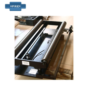
The coil guide control system is a closed-loop controller, controller, sensor, and linear guide mechanism forming the basic part of closed-loop control. First, the guide sensor detects the edge or line of the coil, and the system automatically reads the actual position and setting of the coil. The offset at a fixed position is converted into an electrical signal proportional to it and transmitted to the controller. After the signal is amplified and calibrated by the controller, the signal is output to a linear drive. The linear drive drives the guide guide according to the size of the signal. Mechanism to restore the coil to the set position. The current drive signal of the driver is only proportional to the amount of deviation of the coil, which makes it possible to provide accurate control for various coils and correction systems.
-Industrial control systems used in steel, corrugated paper, textile, printing, labeling, labeling, papermaking, plastic film, building materials, cables, rubber, tires and other industries. Guide control refers to the technical operation of the coil produced by the manufacturer to keep the side of the coil neat and consistent during spraying, printing, die cutting, lamination, slitting or other coil winding processes. Because once the edge of the coil is not aligned, it will cause errors in subsequent steps, resulting in material waste or shutdown adjustment. Therefore, when processing and processing coils, it is necessary to perform timely correction operations on the offset coils. This process is called correction. The equipment of the entire process constitutes a correction system. Guide systems cover a wide range, and are essential in industries such as packaging, printing, labels, building materials, pulp, household paper, plastics, clothing, cables, metal processing, non-woven fabrics, and corrugated paper processing. A typical guide system includes a guide controller, a guide sensor, a guide frame, and a driver.
Previous: What Are The Advantages Of Photoelectric Guide Controller?
Next: The Effect Of Well-designed Rubber Bending Rollers Is Obvious