Tel: +86-134-31394972
E-mail: sales@pre-webguidesystem.com
Tel: +86-134-31394972
E-mail: sales@pre-webguidesystem.com

Magnetic powder brake:
Magnetic powder brakes are often used in tension control of "unwinding" shafts. The magnetic powder brake is equipped with a coil and magnetic powder. When the current flowing through the coil is larger, the magnetic field generated by the coil is also larger. Under the action of the magnetic field, the magnetic force of the magnetic powder is larger, and the resistance of the "unwinding" shaft is increased, and the operation is difficult, resulting in difficulty. The tension of the film is increased.
The 0-4A current required for the magnetic powder brake can be supplied by various types of tension controllers and constant current sources (or power amplifiers) produced by our company.
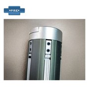
Magnetic powder clutch:
Magnetic powder clutches are often used in tension control of "winding" shafts. The magnetic powder clutch consists of two front and rear discs. The front disc is inextricably connected to the rear disc, and there is also a coil and magnetic powder between them. The front disc is driven by a click, and the rear disc is connected to the reel. When the current passing through the coil in the magnetic powder clutch is zero, the front disc is rotated by the motor, and the rear disc can be rotated or turned very slowly, that is, in a "slip" state, when the coil in the magnetic powder clutch passes When the current is current, the coil generates a magnetic field. Under the action of the magnetic field, the magnetic disk starts to run or the rotation speed increases. The larger the current passing through the coil, the faster the rear disk rotates, that is, the faster the "winding" axis rotates. The tension of the film is increased.
The 0-4A current required for the magnetic powder clutch is also provided by various types of controllers and constant current sources produced by our company.
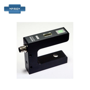
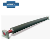
Floating roller potentiometer:
The floating roller potentiometer is actually a “position sensor”. It has the same point as the ordinary potentiometer and has three connection points, and the middle is a "sliding connection point (sliding arm)". The difference is that the floating roller potentiometer is a wire wound, very linear linearity potentiometer with a linearity of 0.2% -1%. A gear will be mounted on the shaft of the floating roller potentiometer, and the secondary gear will float. The gears on the rollers match. When the floating roller moves up and down from the horizontal position, the sliding arm of the floating roller potentiometer also slides up and down. The upper and lower ends of the potentiometer are applied with a voltage of 10V. When the floating roller is in the horizontal position, the voltage of the potentiometer sliding arm to the ground is 5V, and the sliding roller of the floating roller potentiometer when the floating roller is offset from the horizontal position upward or downward The voltage may also deviate from 5V, or increase, or decrease. The magnitude and direction of the floating roller deviating from the horizontal position can be known from the magnitude and direction of the potentiometer sliding arm potential. Therefore, the floating roller potentiometer will be in the middle. A bit amount sensor.
Previous: Precautions For Installation And Use Of Tension Sensor
Next: How To Use Magnetic Powder Clutch And Tension Controller