Tel: +86-134-31394972
E-mail: sales@pre-webguidesystem.com
Tel: +86-134-31394972
E-mail: sales@pre-webguidesystem.com
The steel strip position sensor detects the edge of the steel strip, and the detection result is sent to the microcontroller. The microcontroller calculates the deviation signal and gives the corresponding control signal. The control signal is amplified by the servo driver and sent to the servo motor. The motor drives the intelligent commutation. The valve, the reversing valve drives the cylinder to act to drive the rectification or centering actuator movement to achieve rectification or centering.
The main difference between CPC and EPC is that the CPC centering control system is to ensure that the steel strip is always in the center of the production line, so there are two position sensors. For example, in the centering system on the uncoiler, the position sensors are respectively located in the running steel belt. The two edge positions are equipped with a set of sensor moving devices in order to meet the requirements of edge detection of different width steel strips. The purpose of the EPC correction control system is to ensure that the winding edge is neat during winding, so that there is one position sensor. If the coiler is equipped with a position sensor, it is located at one edge of the running steel strip. In addition, depending on the actual production situation, the EPC correction and the system configuration of the CPC centering device will not be exactly the same.
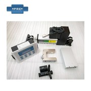
Introduction to automatic correction device selection
1. The hydraulic automatic correcting device is divided into two series: upper correcting and lower correcting;
2. It can be selected according to the one-way transportation of the belt conveyor and the working mode of two-way transportation;
3. Please fill in the supplied parameter list according to the belt conveyor used.
The working principle of the correction system:
The coil rectification control system is a closed-loop controller, controller, sensor, and linear guide mechanism that form the basic part of the closed-loop control. First, the rectification sensor detects the edge or line of the coil, and the system automatically reads the actual position and design of the coil. The offset of the position is converted, and the offset is converted into a proportional electrical signal to the controller. The signal is amplified and calibrated by the controller, and then output to the linear driver. The linear driver drives the correcting and guiding according to the magnitude of the signal. The mechanism returns the coil to the set position. The drive signal of the current drive is only proportional to the amount of deflection of the coil, which allows precise control of the various coils and correction systems.
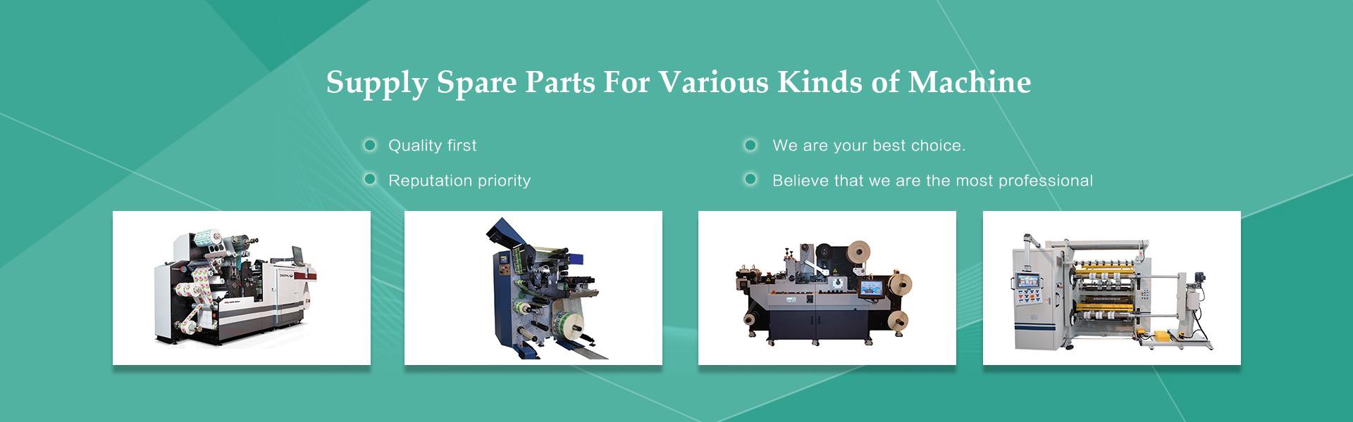
- Industrial control systems for steel, corrugated, textile, printing, labeling, labeling, paper, plastic film, building materials, cables, rubber, tires, etc. Correction control refers to the technical operation of the coil produced by the manufacturer during the spraying, printing, punching, laminating, slitting or other coil winding process, always keeping the sides of the coil neat and consistent. Because the edge of the coil is not aligned, it will cause subsequent step errors, resulting in material waste or downtime adjustment. Therefore, when processing the processed coil, it is necessary to perform a timely correcting operation on the offset coil, which is called rectification. The entire process of the device constitutes a set of correction systems. Correction systems are extremely diverse and are essential in the packaging, printing, labeling, construction materials, pulp, household paper, plastics, garments, cables, metal processing, nonwovens, corrugated paper processing and other industries. A typical correction system includes a correction controller, a correction sensor, a correction frame, and a driver.