Tel: +86-134-31394972
E-mail: sales@pre-webguidesystem.com
Tel: +86-134-31394972
E-mail: sales@pre-webguidesystem.com

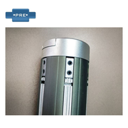
How to install photoelectric guide sensor? The sensor arm is connected to a C-type photoelectric sensor. The mounting material is combined with steel or 200 wide channels. The length of the beam refers to the length of the coil. It is welded on a winding machine. Installation height, left and right position and horizontal distance of coiler, coil or winding according to strip coiling direction, bandwidth change and volume size. Strip coiling, photoelectric frame is installed in low, rolling, installation position. Note the following during installation:
(1) The sensor opening is in the direction of the console;
(2) The receiving electrode is facing up and the emitter is facing down; (looking at the receiving electrode from the window, the receiving electrode is black and the emitting electrode is white)
(3) When the coil diameter is required to be the smallest to the maximum, the upper and lower running trajectories of the strip must be between the emitter and the receiver of the photoelectric sensor;
(4) The front and rear installation positions of the sensor are between the winding head and the entrance guide roller, and it must not interfere with the guide plate;
(5) The left and right positions of the sensor must ensure that the strip specification width changes within the detection linear range.
Install the frame centering position sensor: first push the oil cylinder to the coiler in the neutral position, then fix the position sensor to a certain empty position on the base of the coiler, and then weld the sensor to sense the iron piece on the coiler and follow it. The iron piece is rectangular and wide One edge of the surface is aligned with the middle of the sensor, and the long side should cover the sensor to ensure that when the cylinder moves left and right, the sensing surface of the iron piece will change positively and negatively. The gap between the sensing piece and the sensor is 4-6mm.
1. System debugging.
1. After checking the system wiring is correct, first close the control power circuit breaker, the operation station calls to instruct the oil pump to stop, cooling to stop, and correction to stop. The power amplifier is connected to the servo proportional valve: the valve position feedback sensor signal is as follows:
231: + 15V power supply
232: 0V power ground
233: -15V working power
234: Feedback output
The corresponding voltage signal of the feedback output in different installation states is as follows:
Rectification stop: -8.5V
Press to stop: 0V
Manual left shift: -4V
Manual right: + 4V
Frame centering / automatic guide: about 0V
If the photoelectric guide sensor appears stable in one direction and vibration occurs during the operation of the cylinder in the other direction, adjust the W4 inside the power amplifier two clockwise turns.
2. Adjust the motor phase and then close the power circuit breaker. Press the start button of the oil pump and observe whether the motor turns clockwise, otherwise adjust the phase.
3, adjust the system pressure to adjust the relief valve, the system pressure is about 7Mpa, and then lock the handle nut.
4.Adjust the centering point of the rack and move the centering button.The coiler should return to the middle position to stop.If the rack is biased to one end, adjust the zero potentiometer W6 in the PID controller, and monitor the servo control with the multimeter DC voltage file Output terminals 10 and 11 until the voltage value is zero. If the coiler is not stable in the middle position, it means that the system phase is reversed, then replace the in-phase or inverting terminal of the centering signal input terminal. Then adjust W6 and let The coiler is in the neutral position. Adjust the gain potentiometer W5 (clockwise adjustment, increase the gain) to make the system run at a suitable speed. If the gain is too low, the coiler moves slowly; when the gain is too high, the system is centered. Self-excited oscillation will occur.
5. To adjust the manual state, press Manual Left, Manual Right, and observe whether the cylinder moves and moves smoothly. If crawling occurs, it may be caused by air in the cylinder, loosen the deflation nut on the servo proportional valve, and then move the cylinder repeatedly. Several times, let some oil flow out of the vent hole, and then squeeze the air, then lock the nut.
6. Tuning automatic guide
* Adjust the zero position of the panel first to block the light curtain sensor half, the photoelectric signal output is zero, then release the lock of the panel zero potentiometer knob counterclockwise, and then adjust the handle to the middle scale 5, the potentiometer output is zero (signal Source ± 12V DC).
* Open the screen cover of the modem next to the EPC sensor, and then use the multimeter voltage to measure the photoelectric input signal No. 6 terminal corresponding to No. 10 (signal ground). When the light curtain is not blocked, the maximum signal is about 1.5V DC. When all light is blocked, the signal returns to zero. The photoelectric signal is demodulated, amplified, and transmitted to output a standard voltage signal to the servo controller, and the output point No. 9 is connected to the signal ground. All the light is blocked and all are not blocked. The output signal varies between -10V and 10V. If it is not symmetrical or the signal amplitude is incorrect, the zero potentiometer W8 and gain potentiometer W7 can be adjusted to achieve the best state. After adjustment, close the metal cover.
* Adjust servo controller
The principle of the EPC guide system is that the coiler follows the strip change, that is, the coiler moves in the same direction as the strip offset direction, otherwise it can be changed by adjusting the system phase. The simplest is to input the servo controller The photoelectric signal 205 changes the positions of the non-inverting terminal and the inverting terminal.
Adjusting and correcting accuracy. Adjust the correcting gain potentiometer W4 (clockwise adjustment, increase the gain), improve the system's correcting accuracy, the gain is low, the response is slow, the cylinder oscillates at a low frequency, and the strip coil is uneven; if the gain is too high, the system will produce Self-excited oscillation, high-frequency jitter, usually adjusted to a higher system gain, but do not oscillate for the best operating point.
Adjust the zero-correction photoelectric input signal (terminals 205 to 110) to zero, the zero-adjustment potentiometer is zero, and the voltmeter with offset indication must be reset to zero. Otherwise, the zero-point potentiometer W3 in the servo board can be adjusted to achieve the left and right movement of the light curtain sensor. On the obstruction, the pointer meter should swing left and right, and the positive and negative changes.
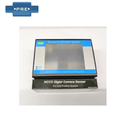
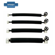
2. Supply PS-500 / photoelectricity guide sensor
PS-500 photoelectric guide sensor
PS-500 photoelectric sensor is based on visible light through-type guide sensor, suitable for edge tracking application of coiled material or line tracking application of transparent material.
Technical parameters of photoelectric guide sensor:
Supply voltage: DC10-30V Output signal: dual 0-5V, dual NPN switch signal
Detection range: 5mm Detection accuracy: 0.05mm
Detection method: Optoelectronic light source: Blue LED / IR Irda
Carrier frequency / response frequency: 100KHz / 1KHz
Degree of protection; IP54
Features:
1, 100K frequency carrier coding, not affected by the environment.
2. Detection range: 5MM, detection accuracy: 0.02mm
3, suitable for opaque, transparent film tracking applications
4.Visible light
5, high stability, high precision
6. Support analog / digital output, can be used with EPC-A10 or EPC-A12 guide controller
Previous: What Are The Operation And Maintenance Requirements Of Photoelectric Correction Sensors?
Next: Advantages In Photoelectric Sensor Detection Applications