Tel: +86-134-31394972
E-mail: sales@pre-webguidesystem.com
Tel: +86-134-31394972
E-mail: sales@pre-webguidesystem.com

The trainer is applied to the lateral deviation control of the web material, and the position of the edge or line is detected by a photoelectric sensor to pick up the deviation signal of the edge or line position. Then the position deviation signal is transmitted to the photoelectric deviation correction controller for logic operation, and the control signal is sent to the mechanical actuator, which drives the mechanical actuator to correct the serpentine deviation of the material during operation and ensure the linear motion of the material. Optional left and right limit switches prevent the system from getting out of control.
Solution:
1: If the sensitivity of the electric eye is reduced, or dust blocks the lens, please clean the electric eye or replace the electric eye.
2: The sensitivity of the system is not enough, under normal circumstances, the film should be shaken at the electric eye, and then adjust the sensitivity adjustment knob on the control box to make it in the best state when it is just to shake and not move.
Solution: Under normal circumstances, LED blue, white, red, etc. have color bias phenomena, and generally do not know the true color, that is, the blue light has the worst blue color recognition, and the yellow light is more difficult to identify the white. At this time, please press and hold the SET button for three seconds, let go and let the photoelectric eye automatically adjust the light source, or need to adjust the sensitivity knob of the control box to increase the sensitivity.
Solution: This phenomenon is generally the damage of the power tube of the control box, check the method: use the manual way to see whether the actuator only goes to one side, if the manual only goes to one side, you need to replace the high-power tube. If you can walk on both sides manually, but only go to one side after the electric eye is connected, the electric eye is broken or the control box is in the wrong direction, replace the electric eye or adjust the control box (it is recommended to send it back for repair).
Solution: If the left and right manual keys are not in position during the manual type, if the 5A fuse tube is intact, it can be judged that the pipe is damaged and the pipe needs to be replaced (it is proposed to send it to maintenance).
Solution: The switching power supply is not added, check whether the 2A/5A fuse tube is burned (broken), or the touch is not very good. (Proposal to be sent to maintenance)
Solution: Adjust the balance potentiometer for multiple turns (5 turns) of the potentiometer, if the direction is wrong, it will never be adjusted to balance. or two potentiometers are broken. (If the imbalance cannot be adjusted in the opposite direction, it is recommended to send it back for repair).
If it is not for this reason, then adjust the position of the correction sensor, you can use the manual way to see if the actuator only goes to one side, yes, you need to change the high-power tube, if you can go on both sides, but the electric eye is connected to only one side, it is the electric eye is broken, or the control box is in the opposite direction.
The trainer mainly corrects the signal by adjusting the DC level, so as to eliminate distortion and skew in the signal. The left and right correction direction refers to the translation direction of the signal after the correction is adjusted, if the translation direction is incorrect, it will lead to unstable signal or unable to transmit normally.
1. Determine the signal transmission path between the signal source and the output device, and turn on the corresponding trainer.
2. By observing the position of the signal waveform, the problem of wrong direction of correction can be determined.
3. According to the manual of the trainer or the guidance of professionals, use the corresponding adjustment tool to adjust the corrector to move the position of the signal waveform to the correct position.
4. Constantly observe the position of the signal waveform and fine-tune it until the signal is translated in the correct direction.
1. Check whether the specifications and models of the switching power supply of the control board of the deviation correction device are paired
2. Check whether the power plug connected to the control board of the deviation correction device is intact
3. Whether the power cord plug is in good contact with the power interface of the control board of the deviation correction device, whether the wiring is appropriate, and plug it again in the future.
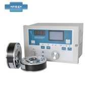
1. Check the coil tension: Make sure the coil tension is not turned on, as this may cause the trainer to shake.
2. Adjust the sensitivity: Press 'Gain +' (← or →) to adjust the gain size, the adjustment range is 1 to 1050, and with each adjustment, observe the change of one indicator until you see one light on and stay the same.
3. Adjust the motor drive speed: Press 'Gain + Set+' (← or →) to adjust the drive speed, the adjustment range is from 1 to 9.
4. Strengthen the mechanical structure: If it is jitter caused by mechanical problems, you can add stabilization brackets, strengthen fixing screws and other methods to improve mechanical stability. 2
5. Replace the optics: If the jitter problem appears on the optics, the damaged optics should be checked and replaced immediately.
6. Isolate interference signals: If an external interference signal causes jitter, the interference can be eliminated by adding an isolation layer or other measures.
7. Optimize the control circuit: optimize the design of the control circuit to reduce circuit noise and signal interference, so that the photoelectric corrector can work more stably.