Tel: +86-134-31394972
E-mail: sales@pre-webguidesystem.com
Tel: +86-134-31394972
E-mail: sales@pre-webguidesystem.com
The tension control system is designed to control the tension to ensure that the factory produces better quality products. For example, the tension controller system function reduces the tension of the paper web in the rewinding zone as the roll diameter increases, eliminating crushed cores and stretching, helping to avoid over-tight or over-loose rolls.
The basic functions of tension control are:
(1) Ensure that the continuous production process can be carried out normally, that is, to ensure that the flow rate of the processed material is equal in each part of the continuous production line, so as to achieve the requirement of neither stacking nor breaking;
(2) Ensure the quality of the processed products, such as dimensional accuracy (thickness, width, cross-sectional shape, etc.), straightness, winding tightness, shape and material performance, etc.
Tension control systems play an important role in different areas:
The tension control system is basically used in industrial machines, such as metallurgy, papermaking, film, dyeing and finishing, weaving, plastic, wire and other equipment. Its role is also very important, in many industries of industrial production, often encounter winding control problems. For example, in the production process of paper, textiles, plastic films, wires, printed matter, tapes, metal strips and wires, etc., the uncoiling and winding tension of strips or wires is very important to the quality of products, so constant tension control is required.
This means that the product is subjected to optimum tension during the winding process and remains the same from start to finish. If the tension is too large, it will cause the tensile deformation of the processed material, and if the tension is too small, the stress between the layers of the coiled material will be deformed, resulting in uneven winding and affecting the processing quality. In strip coiling systems, the tension control system occupies an important place, and it is quite complex.
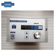
The basic components of the tension control system are:
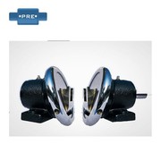
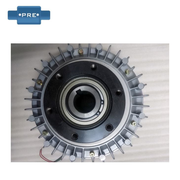
1) Unwinding. Magnetic particle brake/servo motor, uniform unwinding.
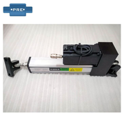
2) Intermediate control. Tension detection, uniform speed traction.
3) Rewinding. Magnetic powder clutch/servo motor, uniform speed winding.
Automatic tension control system control principle: generally can be divided into direct tension control method and indirect tension control method.
1) Direct tension control method: also known as feedback control, it can be divided into two types: a&b
a. Use sensors such as tensiometer to detect the actual tension, and use the measured value as a feedback signal to form a tension closed-loop system, that is, compare the measured actual value with the given tension, and control the deviation to make the actual tension equal to the given tension. The structure of the visual sensor is different, and it can also be divided into position type and feedback type control.
b. Use the looper to establish tension, measure the looper quantity, form a looper feedback control system, control the looper quantity to be constant, and make the product tension constant. This tension control method is suitable for high-precision, high-speed tension control occasions, and has the advantages of high control accuracy and good real-time performance.
2) Indirect tension control method: also known as compensation control, it compensates for possible tension changes through the adjustment of parameters that affect tension stability, and indirectly keeps tension stable, that is, only the tension set value is given, and the actual value of tension is not collected by the detector, and the tension is not closed-loop controlled.
Instead, the tension is indirectly controlled by controlling the current or excitation current of the controlled machine, that is, the driving motor, so that the torque of the motor remains unchanged and the tension of the coiled product is constant.
What are the faults in the process of using the tension control system and their solutions:
1) The tension controller is powered by AC165V-220V, after the current is turned on, if the tension controller cannot work, please check whether the power supply is connected correctly or whether the fuse is abnormal (replaceable).
2) If the signal displayed by the tension controller is incorrect, you can reset the correct signal range, check the route and whether the tension sensor has signal failure or replace the tension sensor.
3) The tension controller has no signal output, usually it is a connection problem, so check whether the signal output connection is correct, and then turn off the voltage for dozens of seconds before powering on.
4) The signal output of the tension controller is unstable, check whether the roller, bearing and magnetic particle clutch/brake/drive are abnormal, replace (reinstall) the tension sensor and recalibrate the signal range.
Precautions for installation of tension control system:
a. Great care should be taken to avoid installation deviations during installation
(1) The upper tightening gland should be carried out after the coupling is aligned, and the bolt should be evenly supported to prevent the end face of the gland from being deviated, and each point should be checked with a feeler gauge, and its error is not more than 0.05 mm.
(2) Check the matching clearance (i.e., concentricity) between the gland and the outer diameter of the shaft or shaft sleeve, and the surrounding area should be uniform, and the tolerance of each point should be checked with a feeler gauge not more than 0.01 mm.
b. The amount of spring compression should be carried out according to the regulations, and it is not allowed to be too large or too small, and the error is required to be 2.00 mm. If it is too large, it will increase the specific pressure of the end face, and the end face will wear at another speed. Too small will cause insufficient specific pressure to play a sealing role.
c. After the moving ring is installed, the mustache ensures that it can move flexibly on the shaft, and it should be able to automatically bounce back after pressing the moving ring to the spring.
Debugging method and steps of tension control system:
1) Program and set the relevant parameters of tension measurement.
2) Make sure that the tension controller is installed and wired correctly and then the power is turned on.
3) By manual adjustment. The system is checked to confirm that the tension display is normal and the actuator is operating normally.
4) Make sure that the tension sensor is installed and wired correctly, and check and judge whether the tension sensor signal is normal.
5) If the above steps are normal, switch to the fully automatic control mode, and adjust the PID parameters according to the operation situation to ensure the balanced operation of the tension control system.
6) Calibrate the 0 point and full-scale range of the tension signal, and determine that the tension display is normal, if the tension display is abnormal, return to the above second step for re-operation.
Precautions when disassembling the tension control system:
a. Be careful when disassembling the mechanical seal, and it is strictly forbidden to use a hand hammer and a flat shovel to avoid damaging the sealing elements. A pair of wire hooks can be made, and the sealing device can be pulled out at the gap of the transmission seat in the direction of self-financing. If the fouling cannot be disassembled, it should be cleaned before disassembly.
b. If mechanical seals are used at both ends of the pump, take care of each other during assembly and disassembly to prevent one from neglecting the other.
c. For the mechanical seal that has been run, if the gland is loose and the seal moves, the dynamic and static ring parts must be replaced, and should not be tightened again and continued to be used. Because after the rotation of the friction pair, the original trajectory of the friction pair will change, and the tightness of the contact surface will be easily damaged.
Application of tension control system in printing industry:
The common printing tension control system is generally composed of magnetic powder brake, tension controller, magnetic particle clutch, tension sensor, motor and other equipment. In the printing transmission system, the same driving shaft drives two printing parts, paper feeding and rolling parts, so that each component can achieve strict synchronous transmission, and the paper belt can basically maintain a stable paper feeding force.
However, due to the differences in printing materials and process conditions, the tension of the paper tape cannot always be stable and consistent by transmission synchronization alone. The tape tension of the printing machine can be changed from the following situations:
1) Replace the paper roll with a new one, so that the tension of the paper tape before and after the change is different.
2) The paper roll has obvious non-roundness, and the radius changes synchronously during rotation, and the use of paper tape is unstable.
3) The change of printing speed will also change the tension of the paper tape. The higher the printing speed, the greater the tape tension, and the slower the printing speed, the smaller the tape tension.
4) The uneven tightness of the paper roll will also affect the stability of the tension.
5) During the printing process, the paper roll slowly changes from large to small.


Previous: Introduction To Tension Controllers, Tension Sensors
Next: It Is Commonly Used in Tension Control Systems On Film Machines